The Logical Workspace
The Logical Workspace is where you will spend the majority of your time building and configuring your network. In conjunction with Realtime Mode, you can use this workspace to complete many of the labs you encounter in your CCNA coursework.
First, you will want to create devices. This is done by choosing devices from the Network Component box. Then, you can do any of the following:
Creating Devices
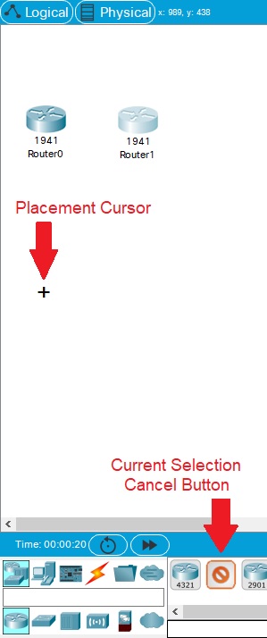
To place a device onto the workspace, first choose a device type from the Device-Type Selection box. Then, click on the desired device model from the Device-Specific Selection box. Finally, click on a location in the workspace to put your device in that location. If you want to cancel your selection, click the Cancel icon for that device. Alternatively, you can click and drag a device from the Device-Specific Selection box onto the workspace. You can also click and drag a device directly from the Device-Type Selection box and a default device model will be chosen for you.

| To quickly create many instances of the same device, press and hold the Ctrl button, click on the device in the Device-Specific Selection box, and then release the Ctrl button. The device is now locked and you can click on the workspace multiple times to add multiple copies of the device. Cancel this operation by pressing the Cancel icon for that device. To duplicate devices, you can press and hold the Ctrl button and then drag a device on the workspace or select the devices and then use the Copy and Paste buttons. |
Moving Objects
To move an object around the Logical Workspace, be sure the Select Tool is selected on the Common Tools Bar. Once the Select Tool is selected, you can left-click and drag items around the Logical Workspace.

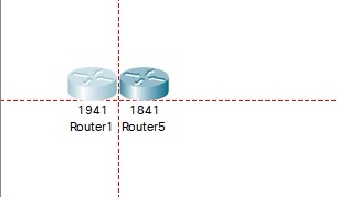
| Logical Workspace objects can also align items when close to other objects. Click and drag on your object and move it close to the object you want to align with. Alignment lines can be enabled in Preferences, under the Interface tab. |
Adding Modules
Most Packet Tracer devices have modular bays or slots into which you can insert modules. In the workspace, click on a device to bring up its configuration window. By default, you will be in the Physical Device View sub-panel of the device. An interactive picture of the device is on the right of the panel, and a list of compatible modules is on the left. You can resize the picture with the Zoom In, Original Size, and Zoom Out buttons. You can also resize the entire configuration window by dragging its borders with the mouse. Alternatively, you can undock the window so that you can move it around and freely resize it. You can browse (by clicking) through the list of modules and read their description in the information box at the bottom. When you have found the module you want to add, simply drag it from the list into a compatible bay on the device picture. You can remove a module by dragging it from the device back into the list.
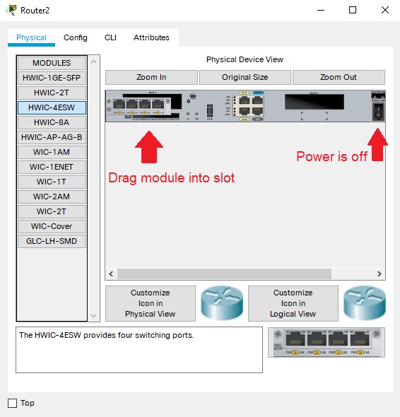
| You must turn off a device (by clicking its power button) before you can add or remove non-hot swappable modules, and you should turn the device back on after you are done. |
Making Connections
To make a connection between two devices, first click the Connections icon from the Device-Type Selection box to bring up the list of available connections. Then click the appropriate cable type. The mouse pointer will change into a "connection" cursor. Click on the first device and choose an appropriate interface to which to connect. Then click on the second device and do the same. A connection cable will appear between the two devices, along with link lights showing the link status on each end (for interfaces that have link lights). If you made a mistake by connecting to an incorrect interface or you want to change the connection to a different interface, click on the link light near the device to unplug the connection from the device. Click on the device again and select the desired interface to reconnect the device. For a full list of connections supported in Packet Tracer, please read the Connections / Links help page.
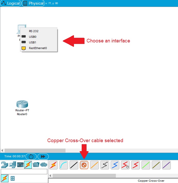
| To quickly make many connections of the same type, press and hold the Ctrl button, click on a cable type in the Device-Specific Selection box, and release the Ctrl button. The connection cursor is now locked and you can repeatedly make the same connection type between devices. Cancel this operation by pressing the Cancel icon for the cable type. |
Logical Topology Editing Tools
You can use the tools in the Main Tool Bar, Logical/Physical Workspace Bar, and Common Tools Bar to edit and annotate your topology.
Tool |
Use |
| Copy | Copy the selected items. |
| Paste | Paste the selected items. |
| Undo | Undo the previous action. |
| Redo | Redo the previous action. |
| Zoom In | Zoom in the workspace. |
| Zoom Reset | Reset the zoom back to default. |
| Zoom Out | Zoom in the workspace. |
| Drawing Palette | Create lines, rectangles, and ellipses. |
| Custom Devices Dialog | Refer to the Creating Custom Devices section above for information. |
| Root | Refer to the Clustering Devices section below for information. |
| Back | Refer to the Clustering Devices section below for information. |
| New Cluster | Refer to the Clustering Devices section below for information. |
| Move Object | Refer to the Clustering Devices section below for information. |
| Set Tiled Background | Refer to the Customizing Icons & BG section for information. |
| Viewport | View a scaled version of the workspace. |
| Environment | Open a dialog that allow you to edit Simulated Physical Environment factors. |
| Select | Click objects and drag them around. This is the default tool. You can also select multiple objects by holding down the mouse button and then dragging your cursor over them. This action draws a rectangle around the objects so you can drag all of them simultaneously. Press the Esc key on the keyboard for quick access to this tool. |
| Move Layout | Move your entire workspace around with the click-and-drag mouse action. |
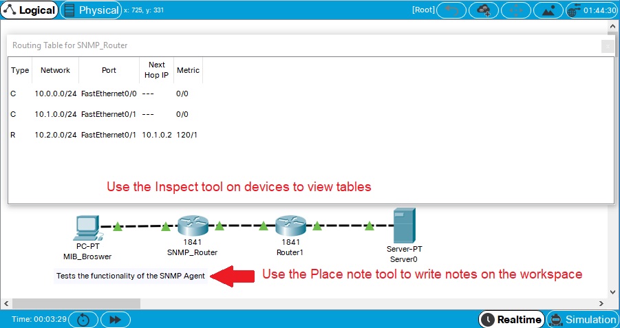
| Place Note | Write and place sticky notes anywhere on the workspace. |
| Delete | Delete objects from the workspace. When you select the Delete tool, the mouse cursor will change into an "X." You can then click on any object (a device, connection, or note) that you wish to delete. |
| Inspect | Look at tables of a device (such as ARP and MAC tables) that have been modeled in this version of Packet Tracer. |
| Resize Shape | Resize shapes that are drawn with the Drawing Palette. When you select the Resize Shape tool, a red square will appear on shapes on the workspace. Drag the red square to either increase or decrease the shape. |
| Add Simple PDU | Refer to the Simulation Mode help section for information. |
| Add Complex PDU | Refer to the Simulation Mode help section for information. |
Configuring Devices
To make most of the devices useful, you need to configure some basic settings (for example, an interface IP address and subnet mask). You can set basic parameters through the GUI configuration screen of the device (click the Config tab from the configuration window). Different devices have different settings available. Refer to each help page of the device for detailed information.
Cisco IOS: Routers and Switches
For routers and switches, you will have access to a model of the Cisco IOS with a limited set of commands. You can use the software to make advanced configurations and view various network information in real time (if you are in Realtime Mode). Here are a few examples of the commands available to you: ping, traceroute, show interfaces, ip access-list, and switchport access vlan. Refer to the Configuring Devices section of the help files for all supported Cisco IOS commands.
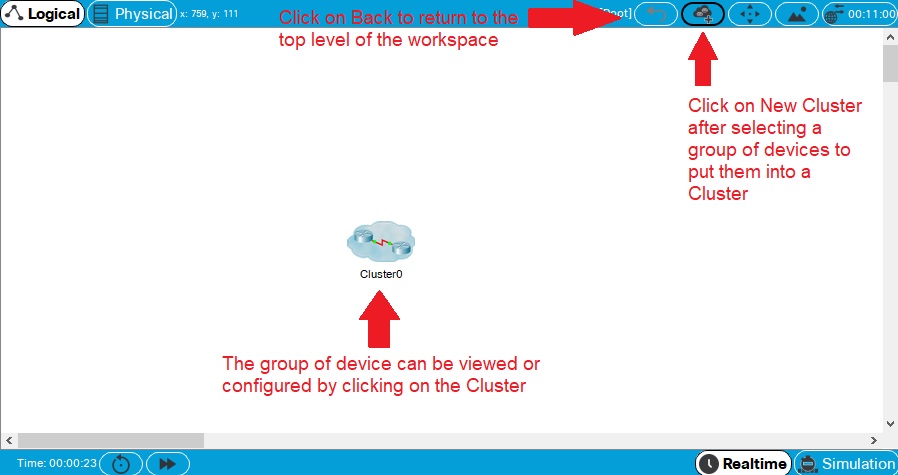
Clustering devices allows you to simplify the appearance of the Logical Workspace by visually reducing a group of devices and connections into a single image. By default, all devices are created on the Logical Workspace are located in the Root level, which is indicated on the Logical/Physical Workspace Bar. You may reduce the amount of clutter on the workspace by clustering multiple devices together with the New Cluster feature. To cluster a group of devices, select the devices on the workspace and then click on the New Cluster button. You can then click on the newly created cluster to go inside its lower level (i.e., Cluster0 by default) and create sub-clusters within the main cluster as well. You may also rename the cluster by clicking on its label to enable the label textbox. You can navigate between levels by clicking on the appropriate level on the Navigation Bar. To uncluster a group of devices, highlight the cluster and then delete it with the Delete tool.
Once you create a cluster, you can make connections to devices in a cluster. To make a connection to devices in a cluster, you first select the connection type and then the cluster. A menu showing the devices in the cluster appears, allowing you to select a device. When you select the device, a menu showing the available interfaces appears. Select the interface and a connection is made if the selected connection type and interface are compatible.
Also, when you can create a cluster, you can move objects and devices within the cluster hierarchy with the Move Object button. To do so, click on the Move Object button and then select an object or device. This opens a menu showing the cluster hierarchy. You can then select the location to which the object should be moved.
Managing Workspace Clutter (Docking/Undocking Sub-windows)
There may be times when you need multiple windows open on your screen (especially when you start running simulations and have to keep track of many things at once). To minimize the visual clutter, you can arrange popup and sub-windows in various ways. Many windows can be docked to or undocked (floated) from the workspace. You can drag floating windows (via their title bar) and dock them to the left, right, or bottom edge of the workspace. Simply drag a window by its title bar until your cursor is near an edge and then release the mouse button. The window will dock to that edge. To undock a window, drag the window by its docked title bar and move it out of the workspace edge to anywhere on your screen.
Some more hints regarding docking and undocking windows:
|