Connections / Links
Packet Tracer supports a wide range of network connections. Each cable type can only be connected to certain interface types.
| Cable Type |
Description |
| Console connections can be made between PCs and routers or switches. Certain conditions must be met for the console session from the PC to work: the speed on both sides of the connection must be the same, the data bits must be 7 for both or 8 for both, the parity must be the same, the stop bits must be 1 or 2 (but they do not have to be the same), and the flow control can be anything for either side. | |
| This cable type is the standard Ethernet media for connecting between devices that operate at different OSI layers (such as hub to router, switch to PC, and router to hub). It can be connected to the following port types: 10 Mbps Copper (Ethernet), 100 Mbps Copper (Fast Ethernet), and 1000 Mbps Copper (Gigabit Ethernet). | |
| This cable type is the Ethernet media for connecting between devices that operate at the same OSI layer (such as hub to hub, PC to PC, PC to printer). It can be connected to the following port types: 10 Mbps Copper (Ethernet), 100 Mbps Copper (Fast Ethernet), and 1000 Mbps Copper (Gigabit Ethernet). | |
| Fiber media is used to make connections between fiber ports (100 Mbps or 1000 Mbps). | |
| Phone line connections can only be made between devices with modem ports. The standard application for modem connections is an end device (such as a PC) dialing into a network cloud. | |
| Coaxial media is used to make connections between coaxial ports such as a cable modem connected to a Packet Tracer Cloud. | |
| Serial connections, often used for WAN links, must be connected between serial ports. Note that you must enable clocking on the DCE side to bring up the line protocol. The DTE clocking is optional. You can tell which end of the connection is the DCE side by the small “clock” icon next to the port. If you choose the Serial DCE connection type and then connect two devices, the first device will be the DCE side and the second device will be automatically set to the DTE side. The reverse is true if you choose the Serial DTE connection type. | |
| The 8-port asynchronous cable provides the high-density connector on one end and eight RJ-45 plugs on the other. | |
| A cable for connecting Things, components, microcontrollers (MCU-PT), and single board computers (SBC-PT). The cable bundles the ground, power, and data wires. | |
| USB cable used for connecting Things, components, microcontrollers (MCU-PT), and single board computers (SBC-PT) as a data connection. |
Wireless Links
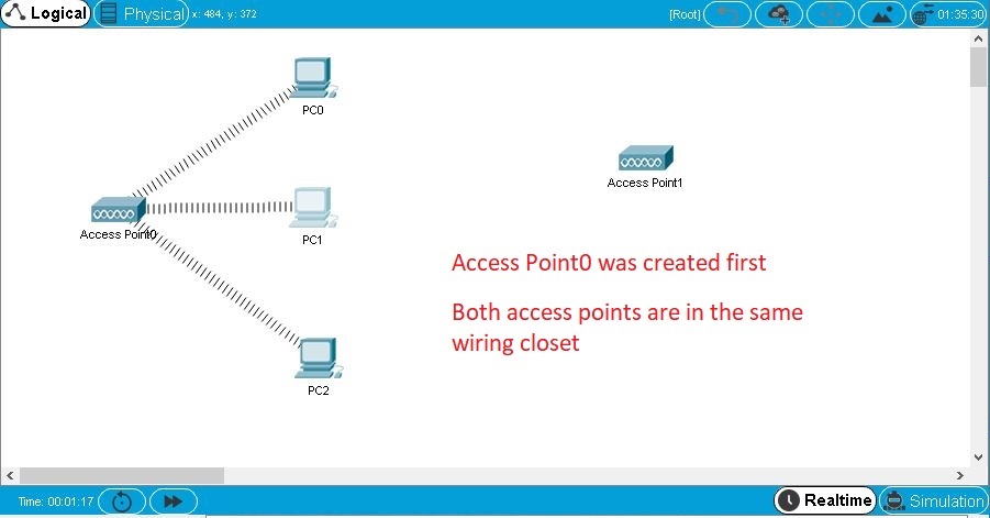
You can establish wireless links between access points and end devices (PCs, servers, and printers). To establish a link, simply remove the existing module on an end device, insert a wireless module, and turn on the device. The device will automatically try to associate itself with an access point. Typically, this means it will associate (physically) with the nearest access point. See the Wireless Devices page under the Physical Workspace section for more information regarding distances. However, if two or more access points are in the same closet, the distance from any access point to any end device is essentially the same. In this case, an end device will associate with the access point that was created first. Recall that the logical topology does not reflect physical distances, and everything that is created in the Logical Workspace is initially placed in the same wiring closet in the Physical Workspace. The process for establishing wireless links between WRT300N routers and end devices with WRT300N network modules is similar, but described elsewhere.

Link Status
When you connect two devices, you will typically see link lights on both ends of the connection. Some connections do not have link lights.
| Link Light Status |
Meaning |
| Bright Up Green Triangle | The physical link is up. However, this is not indicative of the line protocol status on the link. |
| Blinking Up Green Triangle | There is link activity. |
| Down Red Triangle | The physical link is down. It is not detecting any signals. |
| Round Amber | The port is in a blocking state due to STP. This appears only on switches. |
| Round Black | This is used by console connections only. Black color indicates the console cable is connected to the correct port. |