我的第一个Packet Tracer项目
介绍
欢迎使用Packet Tracer。
事实证明,刚开始使用Packet Tracer时先了解一些基本操作的用户会学到更多东西。
本项目旨在使用户熟悉Packet Tracer的功能。
本项目完成需要大概30分钟。
查看帮助文档可以独立完成项目,或者查看视频教程。
项目目标
专业术语(Important Terminology)
-
ICMP ping: 该指令由一台设备发出请求到另一台设备,并显示出另一台设备的回复
-
IP地址:分配给设备的32bit地址,作为网络中的标识。
-
以太网(Ethernet):硬件通信和网线连接的最常见LAN标准之一。
-
高速以太网口(Fast Ethernet Interface):100 Mbps以太网端口。 在Packet Tracer中,GUI中可配置此类接口。
-
OSI模型:(Open System Interconnect),即开放式互联,是ISO(国际标准化组织)制定的一个用于计算机或通信系统间互联的标准体系。OSI为网络开放系统定义了七层结构:应用层,表示层,会话层,传输层,网络层,数据链路层,物理层。
-
PDU:协议数据单元,是指在分层网络结构,例如在开放式系统互联(OSI)模型中,在传输系统的每一层都将建立协议数据单元(PDU)。
-
包(Packets):OSI第3层协议数据单元。 在Packet Tracer模拟模式下以信封表示。
-
设备表(Device Tables):包含有关网络中设备和协议信息。如:ARP,交换机和路由表。
-
ARP 表:地址解析协议-ARP(Address Resolution Protocol)表,存储IP地址和MAC地址的配对。
- 方案(Scenario):一种拓扑,在网络中放置了一组PDU,以在特定时间发送。 使用不同的场景,使用相同的基本拓扑尝试数据包的不同组合。
一、查看帮助和教程
- 启动Packet Tracer。
- 点击菜单栏上,Help->内容,或者按下F1,来查看帮助
- 帮助文档左侧导航栏可以快速在多个页面间切换。浏览入门,以了解Cisco Packet Tracer的基本功能
- 介绍下的“更新内容”部分概述了此版本的Packet Tracer中已添加的功能。
- 请仔细查看“入门”下的“界面概述”部分,以快速熟悉Packet Tracer界面。
- 浏览教程查看Packet Tracer中的各个组件如何工作。
-
点击“在线讲解(英文)”教程,以学习Packet Tracer基础知识。
注意:本教程需要Internet访问,并且某些浏览器可能会阻止本教程的播放。 配置浏览器以允许活动内容来启用网络教程。
- 单击“播放”按钮以开始教程。 然后单击暂停。
-
按下“播放”按钮继续观看教程。
也可以通过向右拖动滑块来跳过本教程的某些部分。
如果需要,请单击“倒带”按钮以重新启动教程。
- 单击Exit(X)以关闭教程窗口。也关闭帮助内容。
祝贺您了解了更多有关资源的信息,这些资源将帮助您充分利用Packet Tracer。
二、创建首个网络
- 点击“File->新建”以新建一个网络,首先选择[终端设备]。 将“PC-PT”和“Server-PT”添加到工作区。
-
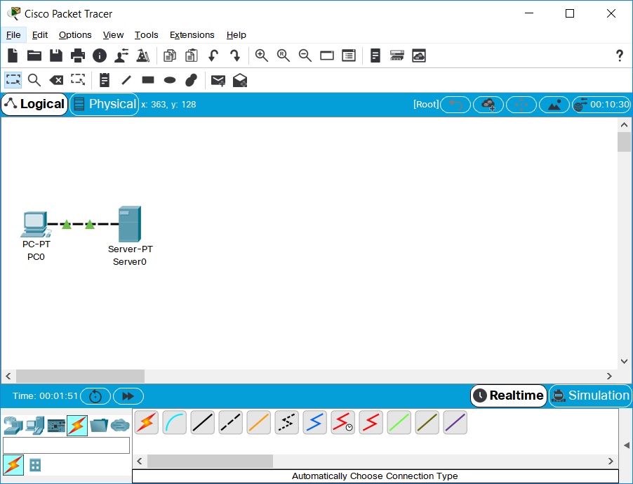
在[连接]下,选择直通线(黑色实线),将设备互相连接。链接上的红灯表示连接无效。
现在,使用删除工具删除直通线,然后改用交叉线(黑色虚线)。此时,指示灯应变为绿色。
如果将光标悬停在任一设备上,则链路状态将显示为“启用”。
现在的连接看起来应该是这样的:
-
点击PC。按下开机键的同时关注连接指示灯状态(如下图),然后再次点击。
然后,对服务器进行相同的步骤。
设备关闭时,链接指示灯将变为红色。
这意味着链接断开或不可用。
重新打开设备电源后,链接指示灯将变成绿色。
-
有三种方法查看设备信息:
光标悬停在设备上,将显示设备基本信息。
使用“选择”工具单击设备将显示设备配置窗口。
使用“检查”工具查看周围的网络构建表。
在此示例中,打开ARP表。由于尚未配置设备,因此ARP表为空。
请在查看完毕后将窗口关闭,不然的话工作区会非常混乱。
-
单击PC打开配置窗口,切换到“配置”选项卡。
将显示名改为“客户端”并将DNS服务器设置为192.168.0.105。
在“接口”下,单击“FastEthernet0”,并将IP地址设置为192.168.0.110。
Packet Tracer将自动计算其他参数。
请确保选中了“端口状态”框。
请查看其他的以太网接口设置(例如带宽,双工,MAC地址和子网掩码)可以在此窗口进行修改。
- 转到桌面选项卡,然后单击IP配置。 请注意,这里也可以更改IP地址,子网掩码和DNS服务器。
-
单击Server打开配置窗口,切换到“配置”选项卡。
将显示名改为WebServer。
单击“接口”->FastEthernet0,将IP设置为192.168.0.105。
确保“端口状态”开启。
单击“服务”选项卡,选择“DNS”,并将“名称(域名)”设置为www.firstlab.com。
将“地址”设置为192.168.0.105,然后单击“添加”。
最后,检查以下“DNS服务”是否打开
-
您可以自由拖动设备来排列位置。
您可以使用主工具栏的“i”按钮(添加网络信息)。
然后,使用“Place Note”工具在“逻辑工作区”中添加一些文本框。
- 点击File->另存为来保存您的项目,并取一个有意义的文件名。
祝贺您已成功创建了第一个网络。
三、以实时模式发送简单的测试消息
- 首先打开上一节保存的文件。
-
请注意,该文件以实时模式(Realtime)打开。
使用通用工具栏中的“添加简单PDU(Add Simple PDU)”工具发送一次ping请求到服务器。
由于所有设备都以及正确配置了IP地址,因此服务器会正确响应请求。
-
单击Packet Tracer程序右下角的向左箭头,打开“用户创建的数据包窗口”,以查看ping消息的不同功能,其中包括ping的成功提示。
-
“切换PDU列表窗口”按钮可以显示一个大窗口来查看列表。
这些消息中的一个或多个可以保存为方案。
启动时默认方案为0。
可以用“ i”按钮,添加“场景描述”。
不同的场景允许对用户创建的数据包的不同分组的实验使用相同的拓扑。
-
单击“新建”可创建一个新方案。
新方案最开始是空白的。
-
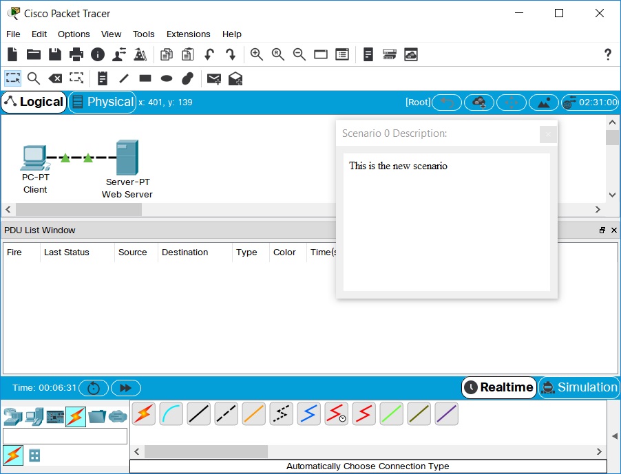
使用“添加简单PDU”工具添加两个数据包,一个从PC到服务器的PDU,另一个从服务器到PC的PDU。
然后按“i”来添加一个场景描述,以完成Scenario 1。
示例如下:
- 单个网络可以保存多个Scenario。也可在多个Scenario之间切换。
- 现在,使用“删除”按钮删除Scenario 0。
-
现在自动转到了Scenario 1。
现在看“PDU窗口列表”中的最后一行,双击“(删除)”以删除单条PDU。
- 单击删除按钮,删除整个Scenario。请注意,当没有Scenario时软件会默认新建一个Scenario 0。
祝贺您能够在实时模式下发送和组织简单的测试消息。
四、使用PC的Web浏览器建立与Web服务器的连接
- 打开在上一节保存的文件。
- 单击PC以查看配置窗口。
-
选择“桌面”选项卡,然后单击Web浏览器。 输入www.firstlab.com作为URL,然后单击“跳转”按钮。 出现Packet Tracer欢迎页面,表明已成功建立Web连接。
-
清除URL,键入www并单击“跳转”。
由于输入的地址不完整,因此会出现信息:“Host Name Unresolved”。
-
URL输入“192.168.0.105”,然后单击“跳转”。
注意,注意,Packet Tracer欢迎页面再次出现了。
这是因为服务器IP地址也可直接用于建立Web连接。
-
关闭窗口,然后在“模拟模式”中尝试相同的步骤。
在这种模式下,用户可以控制时间,因此可以观察到网络运行速度较慢,从而可以观察数据包所经过的路径并详细检查数据包(数据包跟踪!)。
-
通过单击工作区右下角的秒表选项卡进入模拟模式。
再次选择PC,然后转到“桌面”选项卡中的“ Web浏览器”。 再次输入www.firstlab.com作为URL,然后单击“跳转”。 欢迎页面应该还没有出现。
-
在不关闭PC配置窗口的情况下,切换到Packet Tracer的主界面。 请注意,DNS数据包已添加到事件列表。
-
单击“播放控制”->播放键,或反复点击“下一曲”,直到HTTP数据包出现在PC上。
返回到PC配置窗口。
现在显示Packet Tracer欢迎页。
- 关闭PC配置窗口。
祝贺您成功建立了与Web服务器连接。
五、在模拟模式下捕获事件并查看动画
- 打开在上一节保存的文件。
- 在实时模式下,将简单的PDU从PC发送到服务器。
- 使用上一节中学习的方法删除PDU。
- 切换到模拟模式。
-
单击“Show All/None”按钮以取消选中所有字段,然后单击“编辑过滤器”。
然后勾选“ICMP”以仅查看动画中的ICMP数据包。
-
从PC向服务器添加一个简单的PDU。
请注意,新创建的PDU已添加到用户创建的PDU列表中。
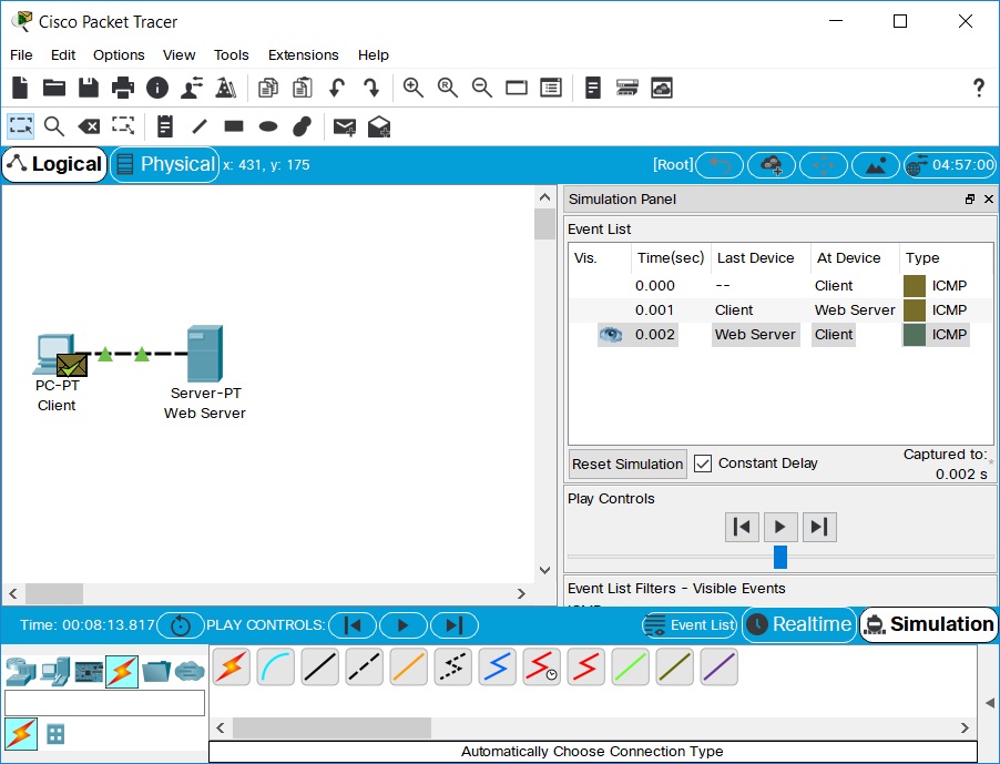
并且,该数据包已被捕获为事件列表中的第一个事件,并且新的数据包图标(信封)出现在工作区中。
事件列表左侧的眼睛图标表示此数据包当前正在显示。
-
单击“播放”按钮一次。
这将模拟网络嗅探程序,捕获网络上发生的下一个事件。
请注意,单击“播放”后,工作空间中的数据包将从一台设备移动到另一台设备(这是从PC到服务器的ICMP回显请求消息)。
在事件列表中添加了另一个事件–这反映了工作空间中的更改。
第一次观看动画,“播放”表示开始捕获;“重置模拟”表示清除之前的。
-
向右拖动滑块加快动画速度,向左拖动减慢动画速度。
-
再次单击“播放”按钮。
这将捕获下一个网络事件(这是从服务器到PC的回复,显示为成功,并在信封上带有绿色的勾)。
-
在此点击“播放”按钮。因为服务器以及回复了请求,所以不会捕捉到更多ICMP事件了。
祝贺您在模拟模式下成功捕获了事件并观看了动画。
六、在模拟模式下查看数据包内部
-
从上一节继续,单击“重置模拟”。
这将清除事件列表中除原始数据包以外的条目。
-
选择工作区上的数据包信封,以显示“设备上的PDU信息”窗口,如下面的屏幕截图所示。
Select the packet envelope on the workspace to show the PDU Information window like the one shown in the
screenshot below. This window contains the OSI Model tab, which shows how the packet is processed at each layer of
the OSI model by the current device. Close this window, noting that this packet is indicated in the event list by
the eye icon. The whole row in the event list is also highlighted. Clicking on the color square in the Info column
is equivalent to clicking directly on the packet envelope (try it!).
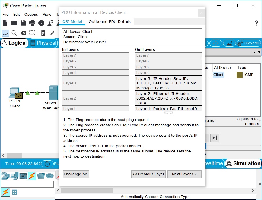
- Use the Next Layer and Previous Layer buttons to see details of the packet processing at the relevant OSI
layers. Note that only the Out Layers can be viewed in the case of this original echo request message.
- Click on the Outbound PDU Details tab. This tab shows exactly what makes up the PDU headers. It is organized
into header type and the individual fields in each header.
- Close the PDU Information window. Click on Capture/Forward button once.
- Click on the packet in the workspace again to open the PDU Information window. Notice that this time,
information regarding both the In Layers and Out Layers can be viewed.
- Click on the Inbound PDU Details tab. This shows the details of the inbound echo request packet from the PC to
the Server. The Outbound PDU Details tab, shows similar information, but for the echo reply packet from the Server
to the PC.
- Click on Reset Simulation again. Now click on Auto Capture/Play. The echo request and echo reply are
automatically captured. Click on the Back Button to rewind the animation one step at a time. Now click on the
Capture/Forward button to forward the packet through the animation. Note the change in the event list and the
workspace. Remember that at any time, a PDU Information Window can be opened by clicking directly on the envelope
on the workspace, or by clicking the Info column in the Event List.
- Click on the Back Button twice to rewind the animation. Now click Auto Capture/Play and the packet animation
will automatically occur.
Congratulations on being able to manipulate the Play Controls and PDU Information Window to understand more about
packet processing details.
VII. Viewing Device Tables and Resetting the Network
- Open the file saved from the previous section.
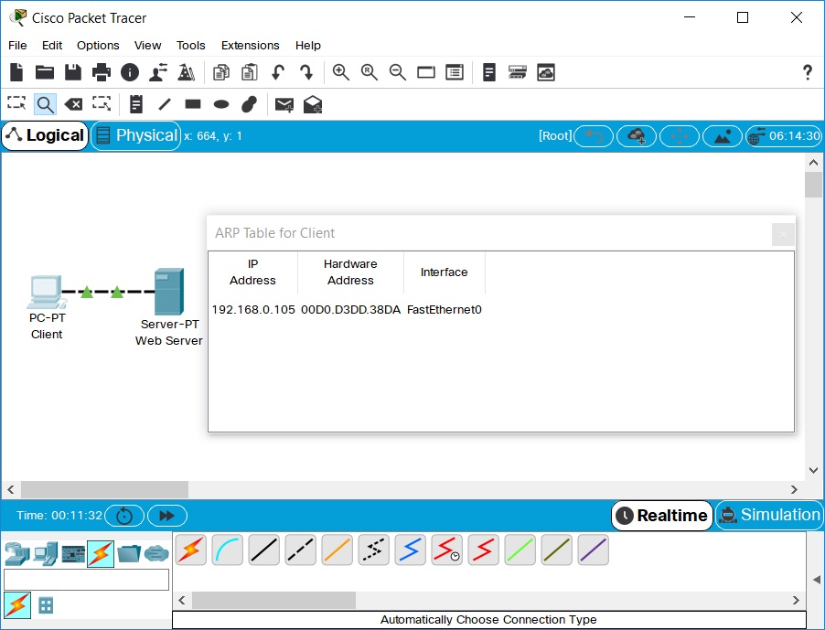
- Open the ARP Tables for both devices by clicking them with the Inspect tool. The ARP tables always appear on the
same spot. Reposition them to make them both visible. You can also resize the tables for better viewing.
- In Realtime Mode, send a simple PDU from the PC to the Server. Notice that the ARP tables are filled in
automatically, as shown here:
- Delete the PDU using the method covered in the previous sections. Notice that the entries in the ARP tables are
NOT cleared. ARP entries for both devices have already been learned. Deleting the user created PDUs does not reset
events what has already occurred in the network.
- Click Power Cycle Devices. ARP tables are cleared because the Power Cycle Devices button turns the devices off
and back on again therefore, losing temporary information like the ARP table entries.
- Go to Simulation Mode. In the event list filters, make sure that ICMP and ARP are checked so that you can view
ICMP and ARP packets in the animation.
- Create a new simple PDU from the Server to the PC.
- Notice that since the devices were power cycled earlier, the ARP tables are empty. ARP request packets need to
be issued before the ICMP ping packets, so that the devices in the network can learn about each other. Click on
Auto Capture/Play to watch the animation.
- Click Reset Simulation. Notice that even though the event list is cleared (except for the user created PDU), the
ARP tables remain full. Click Auto Capture/Play. This time, since the ARP tables are full, there are no new ARP
packets issued.
- Click Power Cycle Devices. Doing so will empty the tables. Notice that new ARP request packets appear
automatically in the event list.
Congratulations! You can now view device tables, reset a simulation, and reset the network.
VIII. Reviewing Your New Skills
- Single-clicking on the Delete button removes the entire scenario including all the PDUs associated with it.
- Double-clicking on (delete) in the far right column in the PDU List window deletes individual PDUs.
- The Reset Simulation button clears all entries in the Event List, except for User Created PDUs, and allows the
animation to restart. This, however, does not reset the device tables.
- The Power Cycle Devices button turns all of the devices in the network off and on so the tables that the devices
built are lost along with configurations and other information not saved.
- Saving work periodically prevents lost configurations and state changes in the network.
Congratulations on being ready to build and analyze many different networks in Packet Tracer! Be aware that there
are many other features that were not covered in this lab. To learn more, please view the other available tutorials
and review the help files. Have Fun!


